


| Kit Details |

Tamiya 1/12 Yamaha YZF-R1 '98/99 - Notes
![]()
|
Model Master Paints Used |
|
Enamel: Chrome Silver (CR) |
Cowling, Tank & Fender
I'm still trying to get in the habit of preparing the bodywork first. These will allow plenty of time for the paint to dry while your attention is turned to the rest of the kit.
All of the bodywork was prepped and assembled. The seam of the rear cowling, tank and front fender were sanded smooth with a Flex-I-File to prevent flat spotting the parts. And I used spot putty to correct an imperfections. The seam in the indentation in the top of the tank is a bit difficult to smooth out. I used a small piece of wet/dry 1000 grit sandpaper under my finger to smooth it out. Everything was then primed with Plasti-Cote Sandable Grey primer.
The inside of the bodywork was painted with my own semi-gloss black (X-18:10 + X-21:1). I made the mistake of painting the yellow first and that made painting the inside more difficult. I brush painted it since masking and airbrushing was too difficult.
![]()
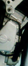
Step #1 - Stand, Engine
Engine block painted with NBS and cylinder head painted with
X-18:10 + X-21:1. The cylinder head is very difficult to mask and there was a risk of
damaging the metallizer so I used wet paper
towel to mask the complex surface. Worked great!
Step #2 - Cylinderhead
The radiator hoses B & C are far too short to be used as
is. They were heat formed to achieve the proper shape. I added Bare-Metal Foil hose clamps.
 Step #3 - Carburetors
Removed the moulded in clutch lever on the
engine cover, C14, and made a replacement. The replacement was made with a straight pin,
some wire for the return spring and pop can aluminum for the lever. A new clutch cable
will be made from wire with the lever end stripped to reveal the wire core.
Electrical line from right engine cover, B16, to left engine cover, C17,
made from #28 wire and painted semi-gloss black. Its the black line just above the engine
cover.
Step #4 - Rear Fender
Painted the rear fender with BEX and sealed it.
Added a backing plate to the taillights and painted it chrome silver on the inside and BEX on the outside. This make the taillights more reflective.
I painted the taillight inside and outside with X-27 Clear Red for a deep clear red.
![]()
Step #5 - Frame Assembly
The plated frame was stripped using Easy-Off oven cleaner
I countersunk the various mounting bolt heads since they have Allen key heads rather than hex heads. I used a #74 drill in a pinvise to do this.
The frame was metallized with BAP. Care was taken to only buff the polished areas of the frame and leave the cast lower portions around the engine. The non-buffed areas were sealed.
Various bolt heads were painted with Dark Anodonic Gray.
Step #6 - Attaching Engine
File the sides on the screws into a hex shape. Once the
engine is installed, fill the Phillips screw heads with CA and paint Chrome Silver so they
look like bolt heads and not model screws.
Step #7, 8 & 9 - Rear Damper, Wheel & Swingarm
On the chain guard, C1, I removed the moulded in bolt head
and made a new one from cutting a disc from stretched sprue.
I stripped the plated swing arm with Easy-Off. The lower shock was painted and then the
swingarm was assembled WITHOUT the wheel and chain. This allowed me to add welds along the
box portion of the swingarm, D12. To simulate the welds I brushed Tamiya Extra Thin Cement
along the joints and then used a straight pin to scribe 'welds' into the softened plastic.
The swing arm was then painted with BAP and buffed with a soft cloth and SnJ's Polishing
Powder. I used a short piece of brass tubing to protect the painted damper when painting
the swingarm.
The chain rings were paint with NBA and the chain was painted with NBDAG. Semi-gloss black was paint in between the links. And finally the chain was rubbed so the pins stand out.
The rear caliper is mould right to the support bracket, but there should be a gap between the two parts. I drilled out the gap with a micro drill and then cleaned the opening up with the X-Acto knife. I also added the brake pad retaining pins by drilling holes with a #74 drill and inserting #28 bare wire.
![]()
Step #10 - Attaching Swingarm
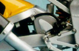 The R1 has
mounting brackets with bushings on the rear brake line. The brackets attach to the
swingarm. I made these from short pieces of radiator hose wrapped with some Coca-Cola can
aluminium for the mounting
The R1 has
mounting brackets with bushings on the rear brake line. The brackets attach to the
swingarm. I made these from short pieces of radiator hose wrapped with some Coca-Cola can
aluminium for the mounting
Step #11 - Exhaust
Assembled the muffler and cleaned up the seam. I then sprayed
NBA along the seam to ensure it was as perfect as possible.
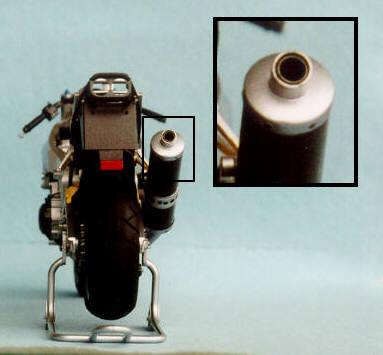 The exhaust has an inner liner and this was added by inserting a short
piece of thin walled brass tubing, painted with Dark Anodonic Gray metallizer.
The exhaust has an inner liner and this was added by inserting a short
piece of thin walled brass tubing, painted with Dark Anodonic Gray metallizer.
Step #12 - Radiator
Added electrical wires for the cooling fan motor.
Added Bare-Metal Foil hose clamps to the left coolant line, C15. The hoses '1' and '3' will require heat forming to have any hope of getting the radiator to fit properly.
Step #13 - Front Wheel
Followed instructions
 Step
#14 - Front Fork
Step
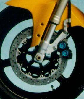
#14 - Front ForkI painted the upper portion of the forks with NBB:1 + NBA:1 first and then masked the metallizer with wet paper towel. Then I painted the bottom ends with NBA and sealed the metallizer. The calipers were painted with BEX and also sealed. The telescopic portion of the forks were painted with Chrome Silver.
Also, the provide screw for the front axle, was replaced with 3/32" brass tubing.
![]()
Step #15 - Steering
On the left grip, C21, I removed the clutch cable stud and
drilled in with a #74 drill for a short piece of #28 wire. On the 1:1 YZF-R1, the control
cables and brake lines have protective sleeves. I simulated this by passing a coated wire
through the kit's vinyl tubing.
The controls were painted with BEX . Then the grips and switches were painted with semi-gloss black. The brake and clutch levers were painted with NBA.
Step #16 - Attaching Front Fork
I modified the instrument panel so I could add a proper
'glass' face over the speedometer. I drilled out the speedometer face then glued in disc
of 0.010 sheet styrene filler. This allowed the decal to be covered with a disc of
clear acetate for the instrument face. An 'face' was also added over the square LCD panel.
Step #17 - Seat, Rear Cowl & Tank
Added 'wrinkles' to the passenger seat, A2, for a much better
look. I masked off the grab strap with masking tape so this would not get 'wrinkles'.
Step #18 - Headlights & Mirrors
I added some wiring to the back of the headlight housing
since this is area is clearly visible after assembling and installing the front cowl.
Step #19 - Upper Cowl
When
assembling the upper cowl, be sure to add the under cowls first. They will act as a jig to
ensure everything aligns properly and stays aligned as the cement dries.
If not done, a large gap will exist at the rearmost part of the upper cowl. I've seen this on most finished YZF-R1 models.
I didn't glue the upper cowl in place, so the join is some of my pictures isn't perfect. I forgot to check it before taking the pictures.
![]()
Step #20 - Attaching Seat, Rear Cowl & Upper Cowl
Followed instructions
Step #21 - Under Cowls
Added 'wrinkles' to the seat, A7, for a much better look.
Markings
Since I haven't done a factory colour scheme, I also varied
the markings. I used the red/black markings (#1, 4, 8, 12, 13, 41, 45, 46, 47) to
represent a '98 Chrome Yellow/Black YZF-R1.
 |
|||||||||||||||
|
|||||||||||||||
 Home - News - Tips - Gallery - Workshop - Kits - Links - What's New? - Site Index |


